How to Draw Cross Section in Autocad
The Export Cross Sections to CAD command is used to automate the batch plotting of all or a selection of cross sections to CAD (i.e., AutoCAD and MicroStation) in a rectangular array pattern. This allows the user to quickly generate cross section plot sheets for his or her projects. This command allows the defined settings to be saved, and then later retrieved, for specific plot requirements.
Follow these steps to export the cross sections to CAD:
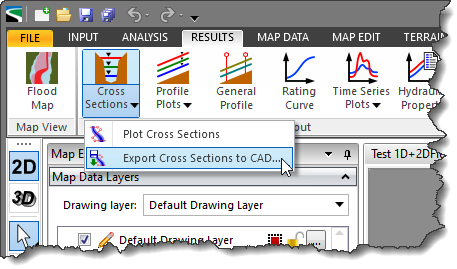
- From the Results ribbon menu, select the Cross Sections menu item and then choose the Export Cross Sections to CAD command.
- The Export Cross Sections to CAD dialog box will be displayed.
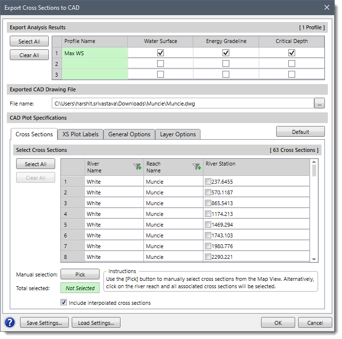
The following sections describe the Export Cross Sections to CAD command and how to interact with the above dialog box.
Export Analysis Results
This section allows the user to select the results to be plotted on the cross sections.
For a steady flow model, the software will list the profiles that were computed. By default, the first listed profile will be selected. However, the user can select the results to be plotted on the cross sections.
For an unsteady flow model, the software will not show any profiles in the table and only the maximum water surface elevation will be exported.
For a steady flow model, clicking the [Select All] button will cause all the available results to be selected. Clicking the [Clear All] button will cause all the results to be deselected.
Exported CAD Drawing File
This section is used to define where the exported cross sections are to be saved.
Click the […] button beside the File name entry to specify the directory location and the drawing file name to save the exported results. Make certain to select the file type, which includes whether to save the file as an AutoCAD or MicroStation drawing file, as well as what file version (i.e., AutoCAD 2013, AutoCAD 2018, etc.).
CAD Plot Specifications
This section is used to define the specifications for the cross sections being exported. Click the [Default] button to reset the specifications back to their default values.
This section is further segmented into four subsections.
Cross Sections
This section provides a table listing the cross sections contained within the model and which allows the user to select which cross sections are to be exported.
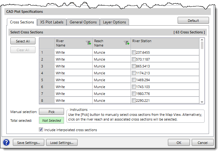
By default, no cross sections are selected. Clicking the [Select All] button causes all cross sections to be selected. Clicking the [Clear All] button will cause all cross sections to be deselected. In addition, the user can manually select from the table which cross sections are to be exported.
Alternatively, the user can click the [Pick] button to interactively select cross sections from the Map View. After selecting the cross sections to be exported, press Enter or right-click and choose Done from the displayed context menu. The user will be returned to the dialog box with the cross sections selected.
Note that the Include interpolated cross sections checkbox entry is used to include interpolated cross sections (those cross sections with a "*" after the river station ID) in the cross section table listing.
XS Plot Labels
This section is used to define the cross section labels to be exported. The user can edit, change, and define labels that will appear on the cross sections.
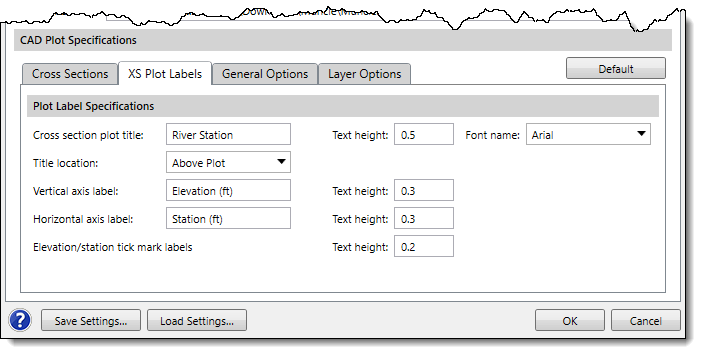
The Cross-section plot title entry is used for defining the cross section plot title. The Title location dropdown combo box entry provides two options for placing the title on the plot sheet: Above Plot and Below Plot. The user can also define the Text height and Font name to be used in the title.
Other options are provided to define the vertical axis label, horizontal axis label, and elevation and station tick mark labels.
General Options
This section is used to specify the tick mark spacing, scaling, and cross section array layout to be used when exporting the cross sections.
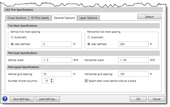
The Tick Mark Specifications section is used for defining the distance between tick marks for vertical and horizontal axes. The software provides two methods: Automatic and User defined.
The Plot Scale Specifications section is used to define the scale to be used for vertical and horizontal axes.
The Plot Layout Specifications section is used to define the gap between the individual cross sections and the number of columns to be used. Units in the spacing entries should match the project units. For example, if the project is in feet, then the cross section grids spacing is in feet.
Number of plot columns defines the number of columns to be created in the rectangular array when creating the cross-section plots. The Export each cross section plot as a block option causes the entire cross section to be a single block, allowing the user to easily move it about within CAD.
Layer Options
This section is used to define the drawing layers (or levels for MicroStation) to be created for the exported CAD drawing.
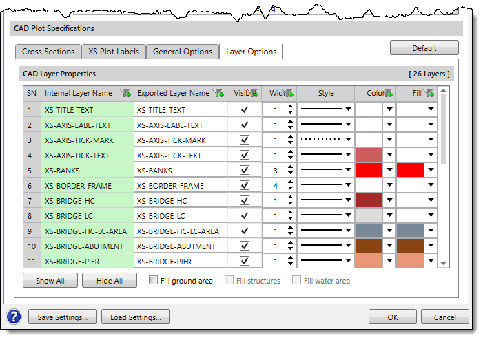
The Internal Layer Name column reflects the internal (read-only) layer name used for reference by the software. The Exported Layer Name column defines the layer (or level) name to be used when constructing the cross section plots. For example, the user may want the exported layer names to be in the French language.
The visibility of the layers can be controlled by [Show All] and [Hide All] buttons. Alternatively, the user can manually select which layers are to be visible.
The Fill ground area, Fill structures and Fill water area checkboxes control the filling of the ground terrain, water, and structures (dams, bridges, etc.) on the cross sections.
Save Settings & Load Settings
The [Save Settings] button allows the user to save the defined settings for later reuse on other projects. The [Load Settings] button allows the user to retrieve previously defined settings.
Exporting the Cross Sections
When all the options have been defined, click the [OK] button and the software will export cross sections to CAD.
Source: https://knowledge.civilgeo.com/knowledge-base/export-cross-sections-to-cad-command/
0 Response to "How to Draw Cross Section in Autocad"
Post a Comment